


1) SERIES CIRCUIT:


2) PARALLEL SERIES
.jpg)
3) OSCILLATOR CIRCUITS

Energy needs to move back and forth from one form to another for an capacitor and an inductor together. If you've read How Capacitors Work and How Inductors Work, you know that both capacitors and inductors store energy. A capacitor stores energy in the form of an electrostatic field, while an inductor uses a magnetic field.
oscillator to work. You can make a very simple oscillator by connecting a
Imagine the following circuit:
If you charge up the capacitor with a battery and then insert the inductor into the circuit, here's what will happen:
- The capacitor will start to discharge through the inductor. As it does, the inductor will create a magnetic field.
- Once the capacitor discharges, the inductor will try to keep the current in the circuit moving, so it will charge up the other plate of the capacitor.
- Once the inductor's field collapses, the capacitor has been recharged (but with the opposite polarity), so it discharges again through the inductor.
This oscillation will continue until the circuit runs out of energy due to resistance in the wire. It will oscillate at a frequency that depends on the size of the inductor and the capacitor.
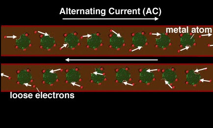
The outlets in our homes provide alternating current (AC).
60 times every second the electrons in the wire change direction.

AC waveform

Direct Current (DC) flows in the same direction all the time
through an electric circuit. Electrons flow continuously
through the circuit from the negative terminal
of the battery to the positive terminal.

DC waveform before smoothing


An electronic filtering circuit in a DC power supply that removes the ripples from AC power.
.jpg)
.jpg)

http://en.wikipedia.org/wiki/Rectifier
Rectifier devices[edit]
Before the development of silicon semiconductor rectifiers, vacuum tube thermionic diodes and copper oxide- or selenium-based metal rectifier stacks were used.[1] With the introduction of semiconductor electronics, vacuum tube rectifiers became obsolete, except for some enthusiasts of vacuum tube audio equipment. For power rectification from very low to very high current, semiconductor diodes of various types (junction diodes, Schottky diodes, etc.) are widely used. Other devices which have control electrodes as well as acting as unidirectional current valves are used where more than simple rectification is required; e.g., where variable output voltage is needed. High-power rectifiers, such as those used in high-voltage direct current power transmission, employ silicon semiconductor devices of various types. These are thyristors or other controlled switching solid-state switches which effectively function as diodes to pass current in only one direction.
Rectifier circuits[edit]
Rectifier circuits may be single-phase or multi-phase (three being the most common number of phases). Most low power rectifiers for domestic equipment are single-phase, but three-phase rectification is very important for industrial applications and for the transmission of energy as DC (HVDC).
Single-phase rectifiers[edit]
Half-wave rectification[edit]
In half wave rectification of a single-phase supply, either the positive or negative half of the AC wave is passed, while the other half is blocked. Because only one half of the input waveform reaches the output, mean voltage is lower. Half-wave rectification requires a single diode in a single-phase supply, or three in a three-phase supply. Rectifiers yield a unidirectional but pulsating direct current; half-wave rectifiers produce far more ripple than full-wave rectifiers, and much more filtering is needed to eliminate harmonics of the AC frequency from the output.

The no-load output DC voltage of an ideal half wave rectifier is:[2]


Where:
- Vdc, Vav - the DC or average output voltage,
- Vpeak, the peak value of the phase input voltages,
- Vrms, the root-mean-square value of output voltage.
Full-wave rectification[edit]
A full-wave rectifier converts the whole of the input waveform to one of constant polarity (positive or negative) at its output. Full-wave rectification converts both polarities of the input waveform to pulsating DC (direct current), and yields a higher average output voltage. Two diodes and a center tapped transformer, or four diodes in a bridge configuration and any AC source (including a transformer without center tap), are needed.[3] Single semiconductor diodes, double diodes with common cathode or common anode, and four-diode bridges, are manufactured as single components.

For single-phase AC, if the transformer is center-tapped, then two diodes back-to-back (cathode-to-cathode or anode-to-anode, depending upon output polarity required) can form a full-wave rectifier. Twice as many turns are required on the transformer secondary to obtain the same output voltage than for a bridge rectifier, but the power rating is unchanged.


The average and root-mean-square no-load output voltages of an ideal single-phase full-wave rectifier are:


